INSTALLATION
Thank you for choosing UniClutch — the revolutionary modular clutch system designed to fit directly to your vehicle’s original flywheel.
To ensure a smooth and successful installation, please follow the general steps below.
Before you begin, download your Vehicle-Specific Installation Instructions for detailed guidance.
For a complete installation, you'll need:
- 1 × UniClutch Core
- 1 × UniClutch Fitment Kit
- Any standard replacement components recommended during a clutch service (not included with the UniClutch system).
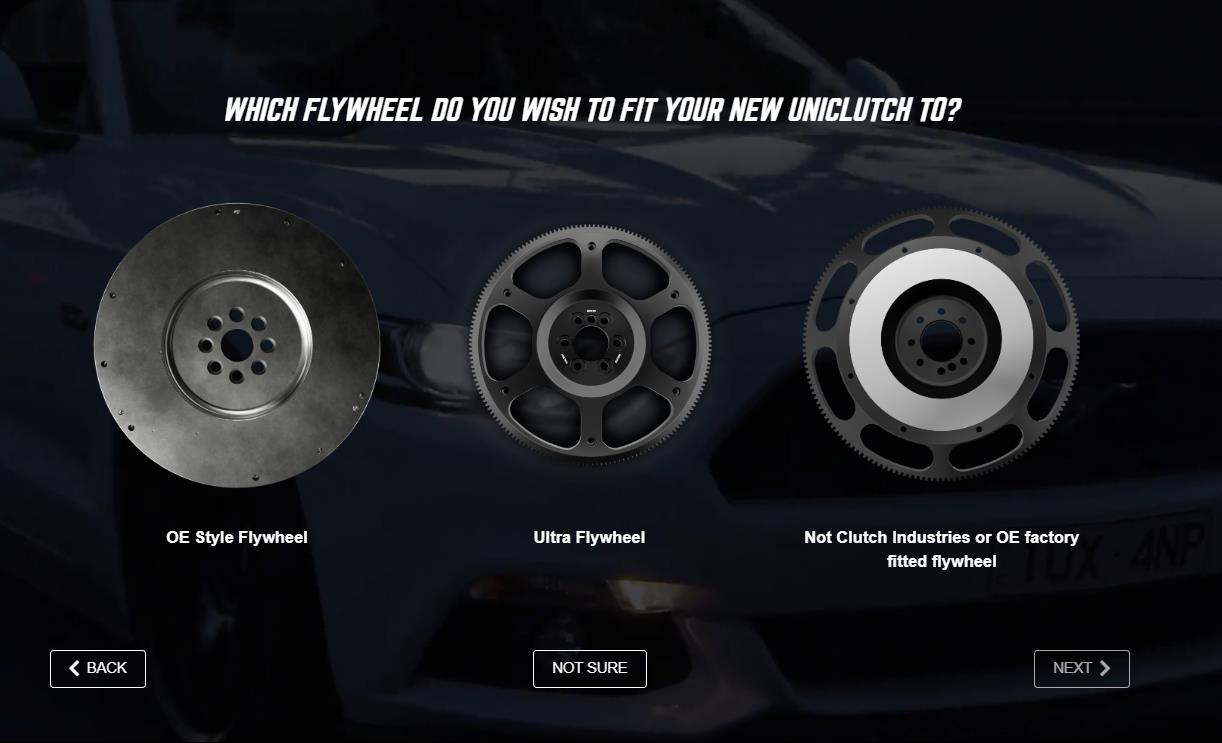
If you’re using a non-OE flywheel, please contact UniClutch Support before installation to confirm compatibility.
If you’re using an Ultra Flywheel, you’re all set — just ensure it’s being fitted to an application where ultra-lightweight, fast-revving performance is desired.
Follow the steps below to learn how to locate and download the correct installation guide for your vehicle.


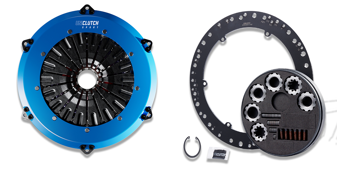
UniClutch Core 8” or 10”
The UniClutch core which best suits your driving style
UniClutch Flex Fitment Kit
The correct fitment kit to suit your vehicle flywheel and gearbox
1
Learn more about our Products
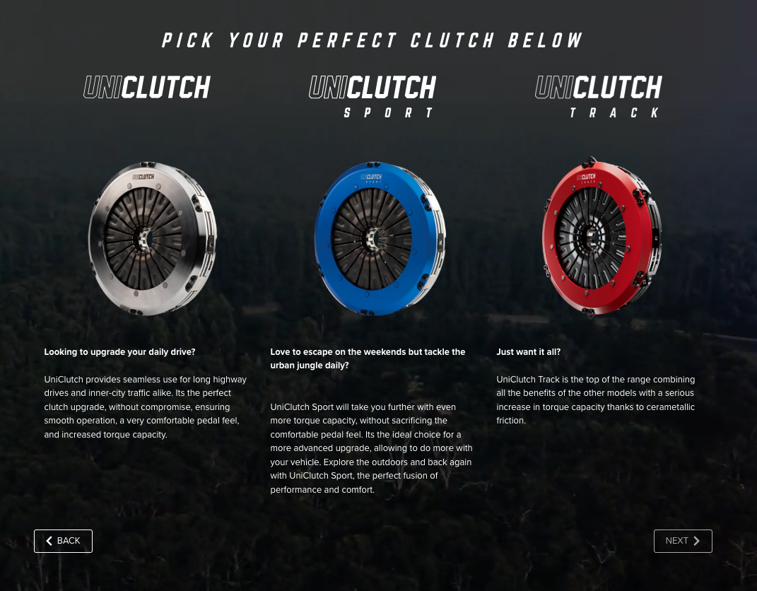
UNICLUTCH CORE
Modular Sealed Clutch Range to suit different driving styles
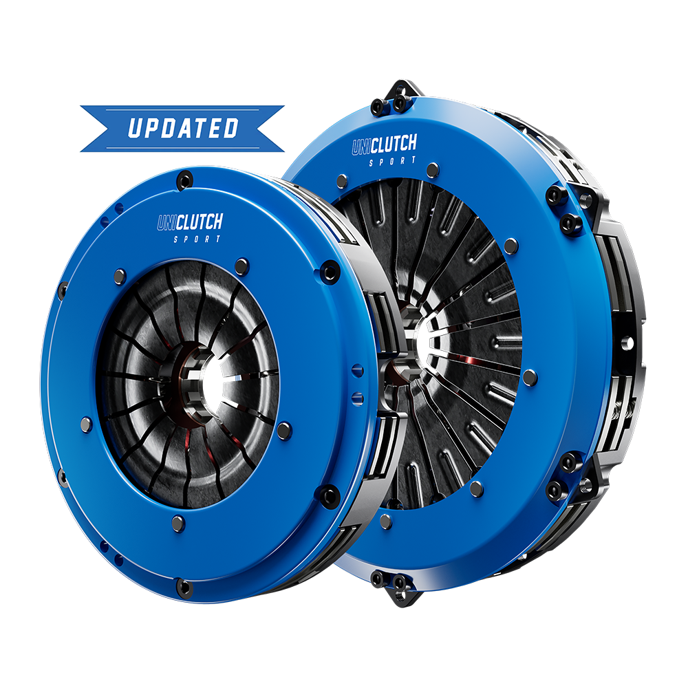

Love to escape on the weekends but tackle the urban jungle daily?
UniClutch Sport will take you further with even more torque capacity, without sacrificing the comfortable pedal feel. It's the ideal choice for a more advanced upgrade, allowing to do more with your vehicle. Explore the outdoors and back again with UniClutch Sport, the perfect fusion of performance and comfort.
Billet Cover
NEW QUAD DRIVE FORGED INTERNALS (NEW UC1024202, UC0824202)
Organic Friction
COMPATIBLE WITH OEM & UNICLUTCH ULTRA FLYWHEELS
8” 610Nm (peak 875)
10” 880Nm (peak 1100)
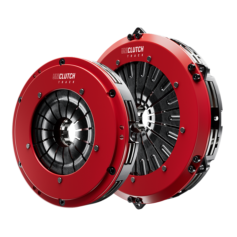

Just want it all?
UniClutch Track is the top of the range combining all the benefits of the other models with a serious increase in torque capacity thanks to cerametallic friction.
Billet Cover
QUAD DRIVE FORGED INTERNALS
Ceramic Friction
COMPATIBLE WITH OEM & UNICLUTCH ULTRA FLYWHEELS
8” 930Nm (peak 1320)
10” 1250Nm (peak 1750)
ICT 1600Nm (peak 2000)

Need a massive torque capacity boost?
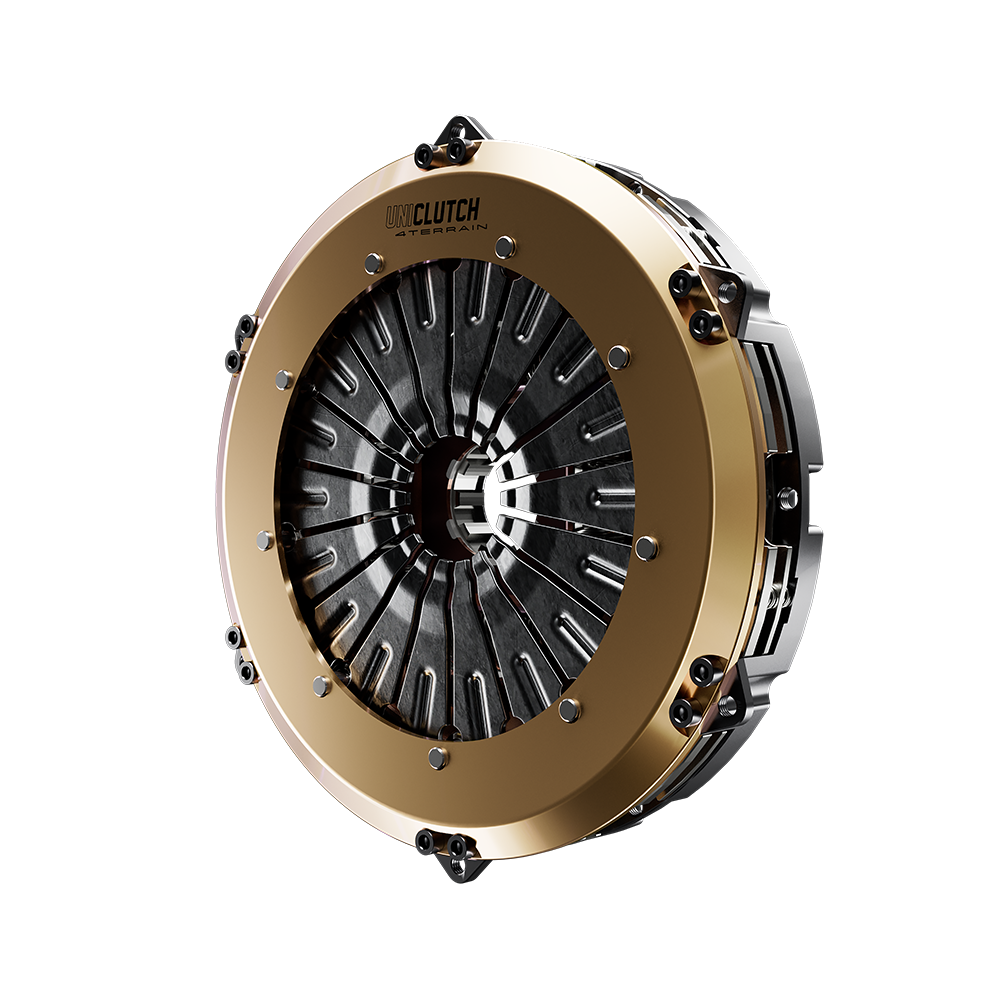
The UniClutch 4Terrain features cerametallic friction for superior torque capacity up to 2000Nm/1450Ft Lb. Perfect for wild offroad adventures where the torque capacity of your old clutch wouldn't cut it.
Billet Cover
PRE-DAMPENER STAGE
QUAD DRIVE FORGED INTERNALS
Ceramic Friction
COMPATIBLE WITH OEM FLYWHEELS
ICT 1600Nm (peak 2000)
UNICLUTCH FLEX FIT KIT
Modular Flywheel & Transmission fitting kits – available to suit a wide range of vehicles
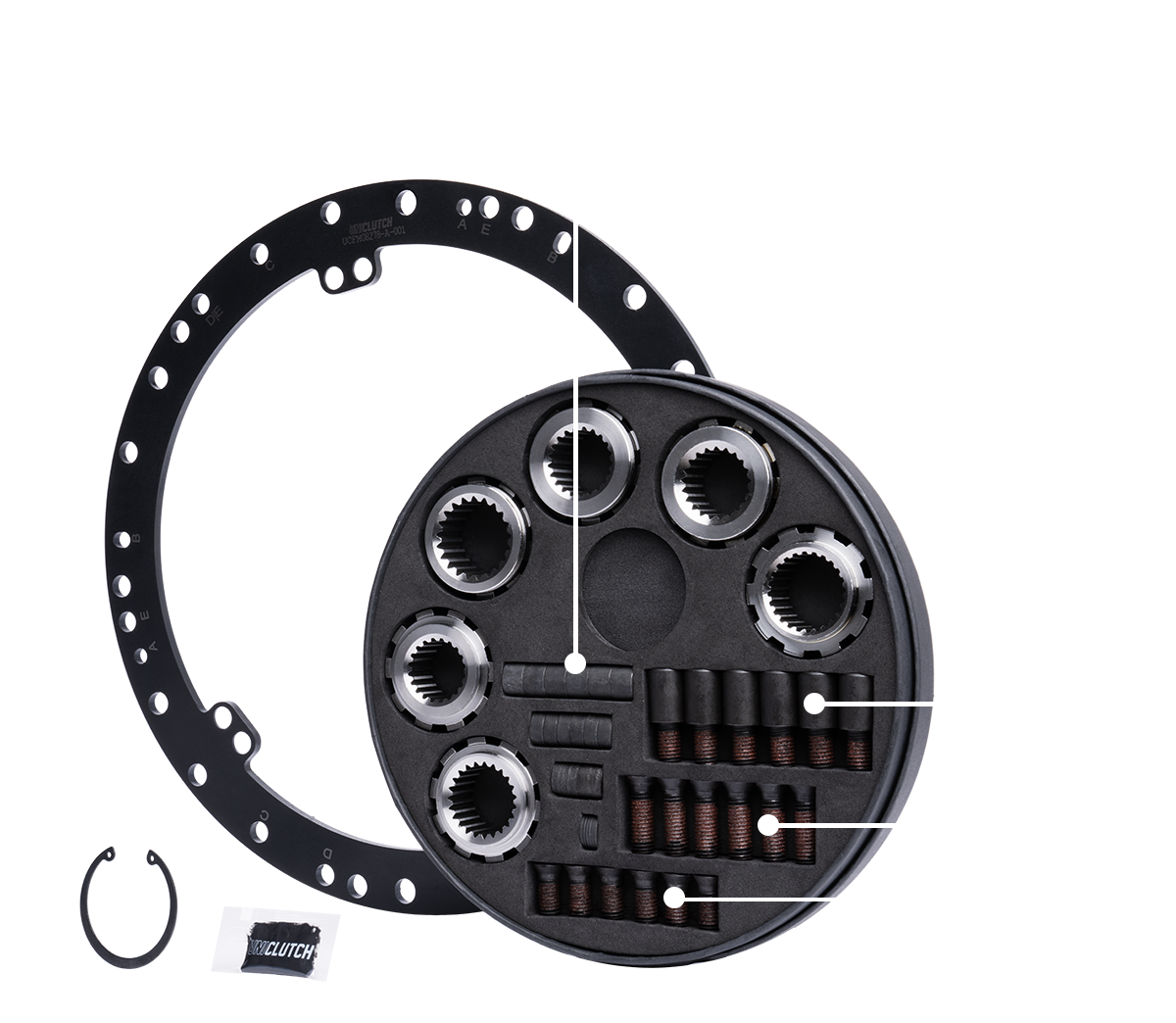
8” Flex Fit System
Spacers for patented height adjustment. Download vehicle specific guide at point of installation for latest spacing setting (CLICK TO VISIT PART FINDER PAGE)
30Nm with calibrated torque wrench. Apply Threadlocker 243 on all threaded components, or 263 for higher RPM use
All Flex Fit Kits include a range of patented interchangeable splines to suit applicable vehicles. Other splines available upon request, 38 types in range
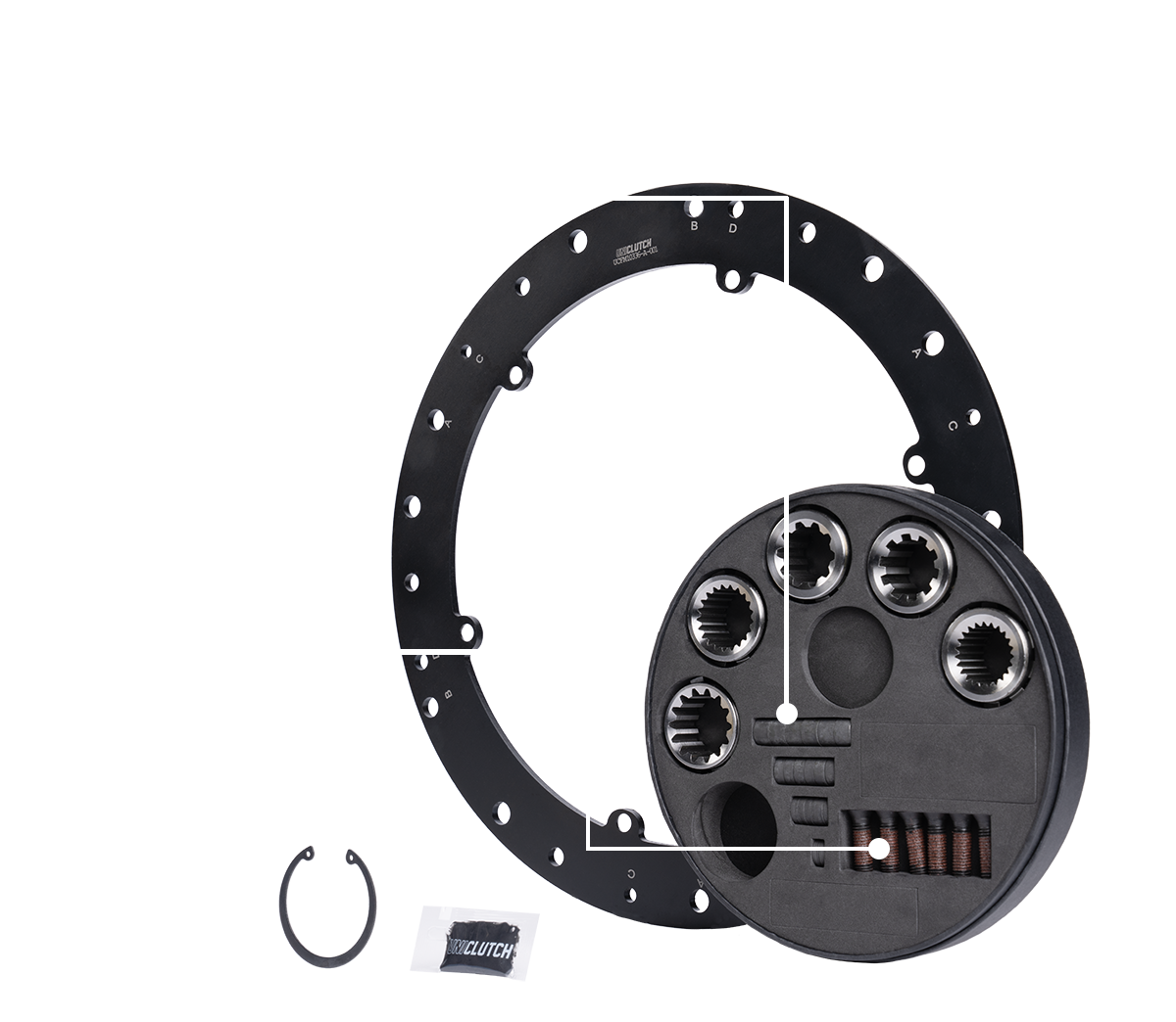
10” Flex Fit System
8” Flex Fit System
Spacers for patented height adjustment. Download vehicle specific guide at point of installation for latest spacing setting (CLICK TO VISIT PART FINDER PAGE)
30Nm with calibrated torque wrench. Apply Threadlocker 243 on all threaded components, or 263 for higher RPM use
All Flex Fit Kits include a range of patented interchangeable splines to suit applicable vehicles. Other splines available upon request, 38 types in range
8” Flex Fit System
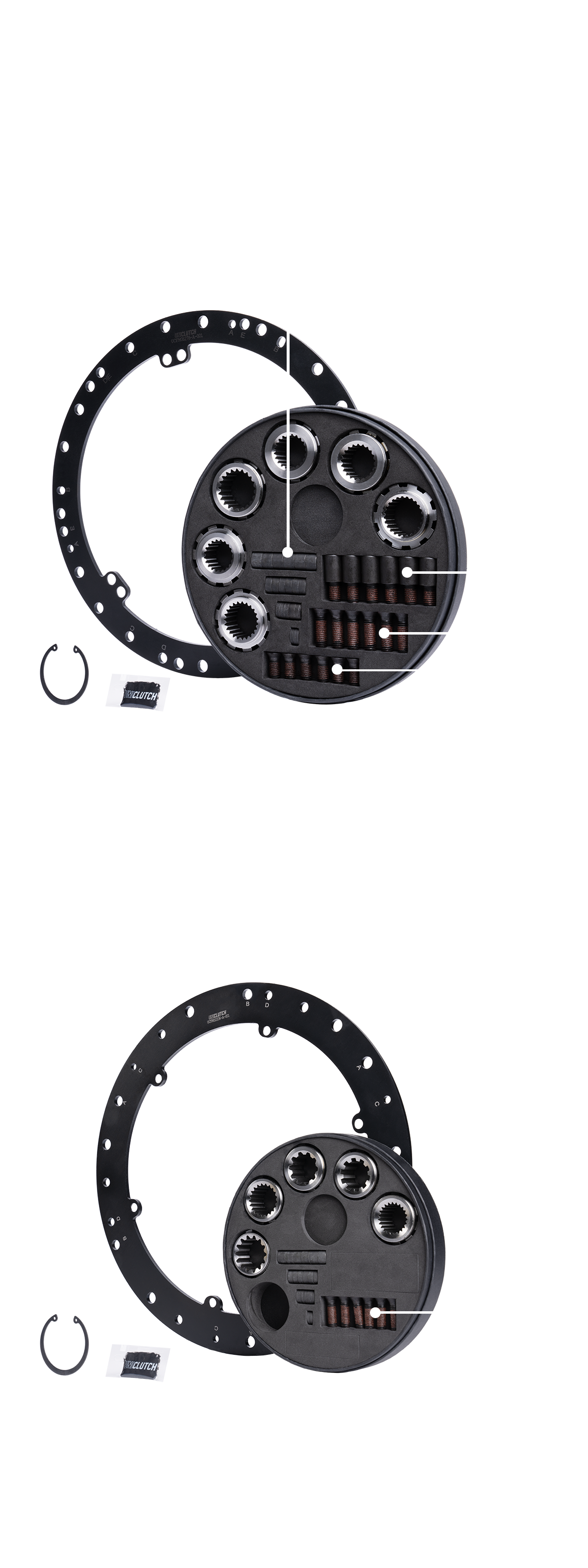
10” Flex Fit System
Spacers for patented height adjustment. Download vehicle specific guide at point of installation for latest spacing setting (CLICK TO VISIT PART FINDER PAGE)
30Nm with calibrated torque wrench. Apply Threadlocker 243 on all threaded components, or 263 for higher RPM use
All Flex Fit Kits include a range of patented interchangeable splines to suit applicable vehicles. Other splines available upon request, 38 types in range
FITMENT TIPS & TRICKS
Flex Fit Kits for OEM spec solid & dual mass flywheels.
Developed to replace OEM clutch pressure plate & clutch disc
Modified vehicles including fitment for non-OEM flywheels may be possible thanks to the Modular design! Ensure you contact UniClutch support or an authorized distributor for assistance before purchasing for a modified vehicle to ensure suitability, and warrantable use.
WATCH THIS VIDEO IF YOU ARE INSTALLING FOR THE FIRST TIME
2
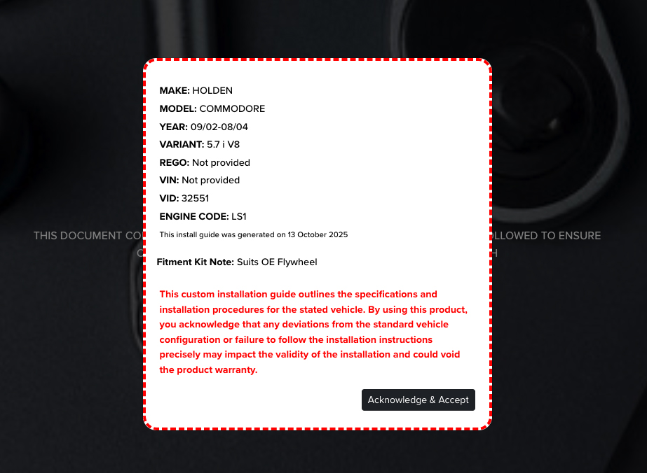
Download the latest Installation Procedure for your Vehicle
STEPS TO FIND YOUR VEHICLE SPECIFIC GUIDE
BELOW WE EXPLAIN THE SIMPLE STEPS TO GENERATE YOUR PERSONALISED UNICLUTCH INSTALLATION GUIDE INCLUDING THE EXPECTED PEDAL FEEL & TORQUE GAINS OF YOUR CHOSEN SETUP.
1. Start by finding your vehicle
EITHER TYPE VEHICLE DETAILS INTO SEARCH BAR OR PRESS MAKE, MODEL OR REGO SEARCH BAR

2. Select the UniClutch you want
3. Select the Flywheel to mount to
4. Download the Installation Guide
To find your specific UniClutch Product & Installation guide Click here
3
General Installation Info and Tips
BELOW ARE GENERIC INSTALLATION STEPS, PLEASE FOLLOW THE ABOVE STEPS TO DOWNLOAD YOUR VEHICLE SPECIFIC INSTALLATION GUIDE.
INSTALLATION STEPS
Preparation
Preparation & Handling
Checklist
- What is the condition of the clutch being removed? Are there any signs of non-clutch (Hydraulics or Driveline misalignment) related issues that could have caused or lead to premature wear or failure?
- Is the hydraulic system properly functioning?
- When the old clutch is being removed are there oil leaks and any signs of red dust?
- Are cracks on the clutch release fork or excessive pivot ball wear?
- Are there any stretch signs on the clutch cable?
- Are the Hydraulic lines in good condition? Are they near heat sources and should be upgraded to braided lines in performance / modified applications?
- Any wearing on release bearing guide tube?
- Anything wrong with the spigot bearing or the pilot brush?
- What is the condition of the Flywheel? Does it have any run our or is the surface straight ?
- Any shipping damage on the clutch?
WHEN FITTING THE CLUTCH, MIND THE INPUT SHAFT SPLINES, CLUTCH SPLINE AND BELL HOUSING:
- Clean the gearbox main drive shaft splines and ensure that the clutch spline slides freely on the shaft.
- Ensure there is not excess play in the input shaft, if there is consider replacing gearbox input shaft bearing before proceeding with Clutch install
- Clean the bell housing: degrease, dust off and remove worn clutch fibres.
- LIGHTLY grease the shaft splines with high temperature grease. Using too much grease may contaminate the clutch plate/disc.
- When installing the gearbox ensure that the gearbox does not put any downward pressure on the clutch and spline in the UniClutch core. If this occurs it can damage the UniClutch spline assembly or put pressure on the circlips which can cause it to prematurely wear or pop out of the UniClutch assembly causing loss in drive.
DRIVELINE MISALIGNMENT
THE MOST COMMON CAUSES OF MISALIGNMENT ARE:
- Missing or damaged dowel pins allowing the transmission to be bolted off centre.
- Mislocated front bearing retainer.
- Foreign matter between the engine block and the transmission mounting faces.
- Missing or worn pilot bearing.
- Broken block flange.
WHAT ARE THE SYMPTOMS OF MISALIGNMENT?
- Pedal graunch with the engine running.
- Deterioration of the clutch until non-release occurs.
- Failed drive plate.
- Red dust covering clutch and/or groove worn in the diaphragm by the release bearing.
HOW DO I PREVENT MISALIGNMENT?
Whenever you are replacing a clutch, inspect the old components. If misalignment is present you will need to find the cause.
- Inspect all dowels and dowel holes for condition.
- Inspect release bearing guide and replace if necessary.
- Clean all mating surfaces.
- Inspect block flange for damage.
REMEMBER:
IF MISALIGNMENT IS PRESENT, FITTING A NEW CLUTCH KIT WILL NOT FIX THE CAUSE OF THE PROBLEM AND THE MISLIGNMENT WILL QUICKLY DESTROY THE NEW UNICLUTCH.
HOW TO CHECK FOR ENGINE/TRANMISSION MISALIGNMENT
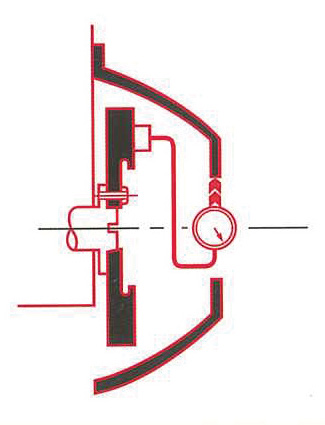
STEP 1
Mount indicator to flywheel and determine concentricity of bell housing bore to centre line of crank rotation, SPECIFICATION: 0.015mm max, T.I.R.
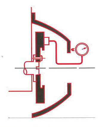
STEP 2
With indicator still mounted to flywheel ensure rear surface of housing is square. SPECIFICATION: 0.15mm max, T.I.R.
REGISTER YOUR UNICLUTCH
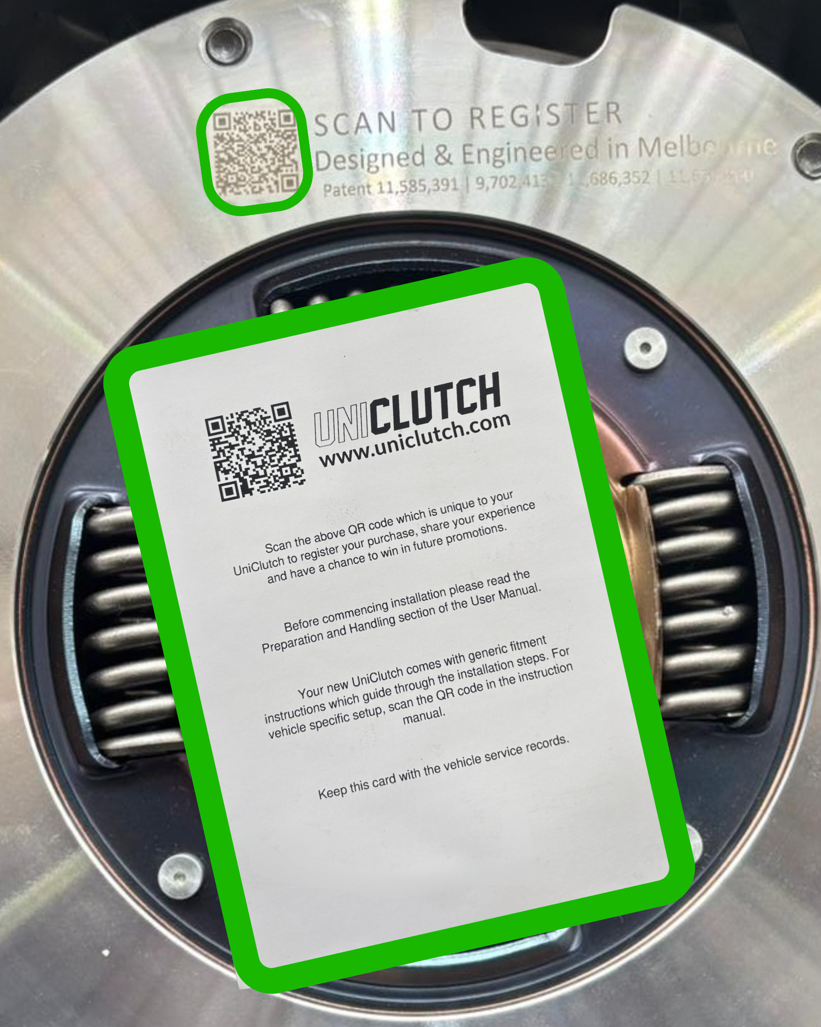
CHECK IN TO YOUR NEW UNICLUTCH
Each UniClutch is 100% tested and marked with a unique QR code. Scan code on the base of the clutch to see the specifications of your unit, including manufacturing date.
INSTALLATION VIDEO
1. INSTALL SPLINE
A. CHOOSE AND TEST
Choose the correct spline for your vehicle. Test fit spline onto input shaft.

B. INSERT
Insert spline into UniClutch

C. Lock in Position
Insert circlip into clutch disc. Make sure circlip has fully expanded in clutch disc and is holding the spline securely before proceeding. Tap the circlip into place to ensure it is fully seated and secured.

ULTRA FLYWHEEL SPECIFIC FITMENT KITS
Only for Ultra Flywheel part numbers UCFW-001, UCFW-002, UCFW-003 & UCFW-004
2. ASSEMBLE UNICLUTCH & FLYWHEEL MOUNT
A. SPACERS
Install spacers in correct order. The spacers required for your application will be found in the vehicle specific installation guide. Measure the spacers to ensure you're using the correct spacer and or tapered bolts as arrange them as per the image on the vehicle specific installation guide.

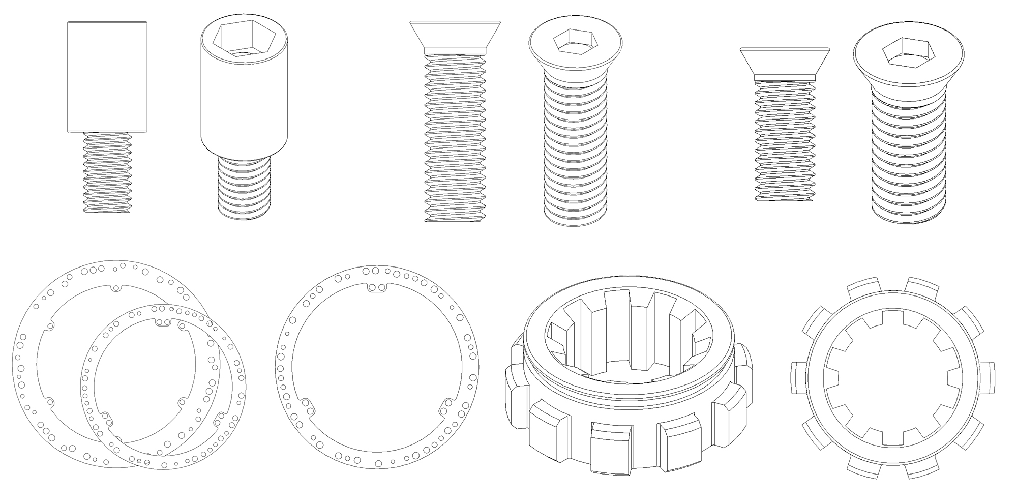
B. BOLTS
You must add Loctite® 243™ or equivalent to all threaded bolts used with the UniClutch flex fit mounting system. Loctite®® 243™ does have a shelf life and if the bottle is old, has not been properly stored or exposed to air it is best to get a new bottle.

C. Torque Fitment kit Bolts
Then install supplied countersunk bolts to secure flywheel mount to UniClutch, torque to 22 Ft lbs / 30 Nm.
BOLTS ARE TORQUE TO YIELD, ONE USE ONLY. If you need another bolt kit, please contact us.
Use a properly maintained, correct-size hex head torque bit to tighten the bolts. Secure the UniClutch core firmly to torque the bolts to the Core and Flywheel mount.

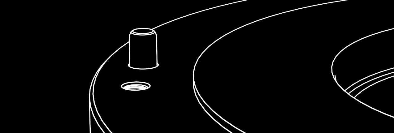
3. IDENTIFY FLYWHEEL
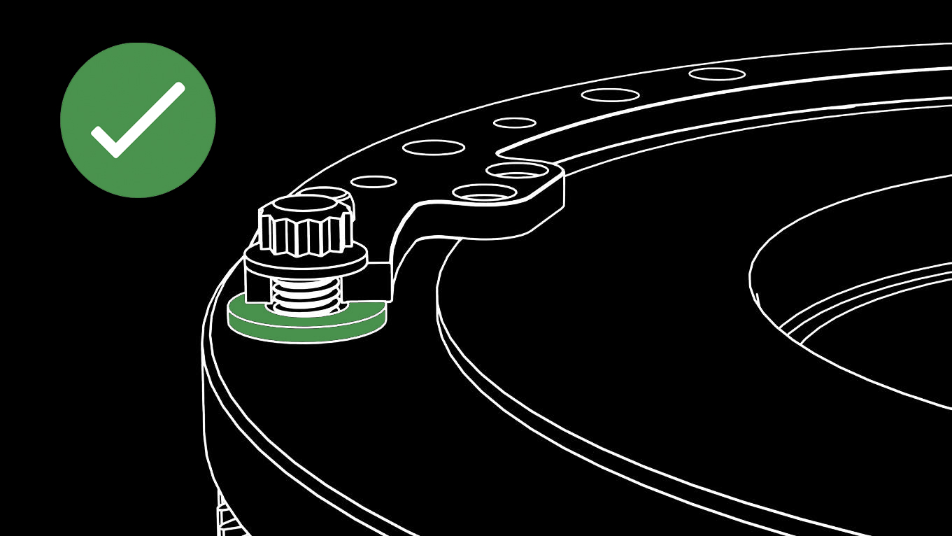
A. Positive Step Flywheel
For vehicles fitted with positive step flywheels, please place washers (not included) between the flywheel mount and the flywheel to prevent excessive bending of the flywheel mount.
Where friction surface of the flywheel is on a higher level than the clutch bolting surface.
B. Without washer between the flywheel mount and the flywheel, UniClutch mounting tab is bent upwards, leading to improper installation.
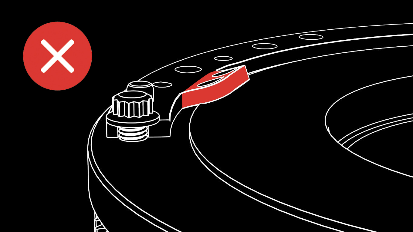
A washer must be added in between the flywheel mount and the flywheel so the UniClutch mounting tab is not bent.
C. In some specific vehicle applications, the flywheel may require machining in order for the UniClutch to be fitted. This is only required in very limited Uniclutch fitments and will be specified in your specific install guide”.
4. BOLT TO FLYWHEEL
A. LOCATE
Locate the correct dowel holes for your vehicle. Download your Vehicle Specific Install Guide to get this.

B. FLYWHEEL
Match Flywheel Mount Dowel holes to vehicle flywheel dowels.

C. SECURE TO FLYWHEEL
Secure UniClutch to flywheel using existing clutch cover bolts and torque to OEM spec.
- Never use left over UniClutch fitment kit bolts or spacers to secure the flywheel mount to the flywheel.
- If you do not have the OEM clutch cover bolts then you will need to source an appropriate bolts. A12.9 grade cap head bolts are required and available everywhere.
- In modified engine, high RPM or race applications it is best practice to use Loctite® 243 on the Flywheel to flywheel mount bolts , especially in applications that have be converted from a Dual mass flywheel to a solid flywheel.
- Engines that are know to have harmonic issues when modified should also observe the same practice as above.

5. FINAL ASSEMBLY
PLEASE NOTE
Whilst changing your clutch, you may wish to replace other worn items.
A. FLYWHEEL
Whilst UniClutch doesn't use the flywheel as a friction surface, you may wish to change your flywheel if it is damaged or out of balance.
B. BEARINGS
Replace any worn out bearings.
CI Release Bearing (Not provided)
CI Spigot Bearing/Bush (Not provided)
CI Release Bearing (Not provided)
CI Spigot Bearing/Bush (Not provided)
Replace any worn out bearings.
RELEASE BEARING/CSC

Use OEM style
Use OEM style
SPIGOT BEARING/BUSH
Use OEM style
Use OEM style
OEM thrust bearing or Hydraulic release bearing / Concentric slave cylinder can be used with the UniClutch system in 99% of installations. Some installations may require a different bearing from OEM, and this will be specified in the specific installation guide for the individual vehicle.
In cases where the UniClutch is being used with an aftermarket or custom release bearing / hydraulic slave cylinder please ensure you contact UniClutch support to confirm suitability before use. Failure to do so may cause UniClutch to not function correct and damage the UniClutch.
Unless stated in the Fitment Kit Notes above, UniClutch suits OEM service parts.
The above Release Bearing or CSC and Spigot Bearing or Bush are references from Clutch Industries Australia. Equivalent OEM spec parts may be used.
C. TRANSMISSION INPUT SHAFT
Ensure Transmission Input Shaft is clean and lubricated very lightly using the grease included with your new UniClutch. Only use a small amount of grease as over greasing input shaft can lead to contamination of UniClutch friction plates when in operation.
Inspect and confirm that the gearbox input shaft end play is within the manufacturer’s tolerance. If end play exceeds tolerance, replace the input shaft bearing and any associated gearbox components before installing the UniClutch. This step is essential for applications where the input shaft is unsupported by a bearing or spigot in the flywheel. Failure to do the above may effect the functionality of the UniClutch and lead to premature failure which is not covered by warranty.
D. VEHICLE SPECIFIC TROUBLESHOOTING
Check if any vehicle specific troubleshooting notes apply. For example; concentric slave cylinder bleeding procedures, etc.
6. BEDDING IN PROCEDURE
This product is a specially engineered Clutch designed to offer an increase in torque capacity while still maintaining a level of drivability often not associated with products of this type. As a result you must ensure that the product is appropiately "broken-in" before heavy or spirited driving. The breaking-in process allows the friction surfaces to mate with each other in order to create full contact and allows the clutch to operate at its intended performance. During the initial bedding in phase, the co-efficient of friction of the clutch discs will drop, and then slowly increase over time to a stable level.
Failure to appropriately break-in clutch may result in glazing or crumbling of the friction surfaces resulting in shudder, slippage and noise during operation and not allow the clutch to transmit the torque to its maximum ability.
To correctly break-in your new UniClutch we recommend operation the vehicle in normal driving conditions such as regular city driving. The clutch must be actuated regularly at low RPM such as take-off and normal shifting for at least the first 500kms. During breakin if the vehicle RPM increases at a rate not proportionate with the normal rotation of the wheels you must back off the throttle to ensure you do not not generate excessive heat. Excessive heat will prevent UniClutch from reaching its full potential.
Warning:
Failure to comply with the bedding in procedure will void the warranty of your UniClutch.
TROUBLESHOOTING
DIFFICULTY CHANGING GEARS
DIFFICULTY CHANGING GEARS
Cause
- The transmission was forced into position damaging the splines of the disc hub.
Repair
- Install new clutch and carefully control the position and alignment during installation.
- Use a transmission jack and possibly install temporary guide pins to assist in aligning the transmission to the engine.
Cause
- Faulty linkage or hydraulics.
- Damaged fork.
Repair
- Replace faulty component.
Cause
- Incorrect spline selected for vehicle.
Repair
- Reinstall correct spline for vehicle.
Cause
- Incorrect height set (finger height too high/too low).
Repair
- Reassemble spacers to achieve correct height.
Cause
- Release Bearing or Concentric Slave Cylinder fitted to vehicle not compatible with UniClutch.
Action
- Contact UniClutch technical support.
Cause
- Clutch is unable to rotate due to interference with clutch fork, bell housing, etc.
Action
- Contact UniClutch technical support.
Cause
- Incorrect release travel. The clutch operating system is badly adjusted, defective or outside the operating range of the UniClutch.
Repair
- Adjust the clutch operating system (pedal height, self adjusting system, clutch linkage..) check the pre-load on the release bearing.
Action
- Contact UniClutch technical support.
NOISE
NOISE WHEN BEARING CONTACTED
Cause
- Seal torn.
- Overheating during slippage.
- Leakage of the grease.
- Incorrect free travel adjustment.
Repair
- Check diaphragm for damage.
RATTLE/RELEASE ISSUE
Cause
- Retaining clip not correctly installed on fork.
Repair
- Install new bearing ensuring bearing is secure to the fork.
NOISE WHEN IN NEUTRAL
Cause
- Lack of care during installation, splines have been damaged by the gear box main shaft.
Repair
- Repair the main shaft.
- Replace the clutch disc.
CAUTION
- Make sure that the splines properly match up.
- Lubricate with a proper quantity of grease.
OTHER TROUBLESHOOTING
TOO MUCH GREASE
Cause
- Excess of lubrication grease on the nose of the release bearing.
Repair
- Clean the release bearing.
- Apply the correct quantity of lubricant.
DIFFICULTY SHIFTING
Cause
- Incorrect release bearing travel.
- The clutch operating system is badly adjusted or defective.
- The level of pre-load on the release bearing is incorrect.
Repair
- Adjust the clutch operating system (pedal height, self adjusting system, clutch linkage..) check the pre-load on the release bearing.
CLUTCH PEDAL BINDING
Cause
- The fork is out of shape.
- The release bearing guide tube is worn or the release arm/fork is bent/worn.
Repair
- Replace by a genuine release fork.
- Install new clutch and guide system components and repair or replace as needed.
THE CONTACT POINT OF THE FORK IS WORN OUT, THE FORK IS OFF-CENTERED.
Cause
- The fork is out of shape.
Repair
- Replace by a genuine release fork.
OTHER
SPARE PARTS
Contact UniClutch Technical Support for any assistance with your installation, including Spare Parts.
TECH SUPPORT
LEGAL
GUARANTEE
Our goods come with guarantees that cannot be excluded under the Australian Consumer Law. You are entitled to a replacement foreseeable loss or damage. You are also entitled to have the goods repaired or replaced if the goods fail to be of acceptable quality and the failure does not amount to major failure.
WARNING:
DO NOT USE ANY CI PRODUCT IN VEHICLES WHICH HAVE BEEN MODIFIED TO EXCEED THE MAXIMUM ENGINE RPM(S) BEYOND THAT WHICH WAS SPECIFIED BY THE ORIGINAL VEHICLE MANUFACTURER WITHOUT FIRST INSTALLING APPROPRIATE SAFETY EQUIPMENT, INCLUDING BUT NOT LIMITED TO TRANSMISSION GUARDS, AS SUCH USE MAY CAUSE THE PRODUCT TO EXPLODE UNEXPECTEDLY CAUSING SERIOUS INJURY AND OR/DEATH.
WARRANTY
STILL HAVING DIFFICULTY?
If you are still having difficulty with installation and use of your UniClutch, or are unsatisfied with your experience, please contact our technical support team [email protected]
WISH TO RETURN YOUR PRODUCT?
If you wish to submit a warranty claim, please contact your place of purchase. Warranty Terms & Conditions can be found at www.uniclutch.com/warrantypolicy
CARING FOR THE ENVIRONMENT
Dispose old or unused parts and packaging in a responsible manner. UniClutch packaging is recyclable.